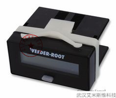
 面板显示仪表
 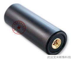 GPS天线
GPS天线  传感器组件
传感器组件  面板安装电阻
  微控制器(MCU)
  电位器
电位器 贴片电阻
贴片电阻 继电器
继电器 交流直流电源
| 无人机飞控设置 PIXHAWK 3DR品牌 PX4连接 | |||||||||||||||||||||||||||||||||||||||||||||||||||||||||
| 3DRobotics > ArduCopter > | |||||||||||||||||||||||||||||||||||||||||||||||||||||||||
| 1 Installing the 3DR UBlox GPS + Compass Module | |||||||||||||||||||||||||||||||||||||||||||||||||||||||||
| 2 Connecting to Pixhawk | |||||||||||||||||||||||||||||||||||||||||||||||||||||||||
| 3 Connecting to APM 2.6 | |||||||||||||||||||||||||||||||||||||||||||||||||||||||||
| 4 Mounting the GPS Module | |||||||||||||||||||||||||||||||||||||||||||||||||||||||||
| 5 Setup in Mission Planner | |||||||||||||||||||||||||||||||||||||||||||||||||||||||||
| 6 Connecting to APM 2.5 / APM 2.0 | |||||||||||||||||||||||||||||||||||||||||||||||||||||||||
| 7 Connecting to PX4 | |||||||||||||||||||||||||||||||||||||||||||||||||||||||||
| 8 LED Indicators | |||||||||||||||||||||||||||||||||||||||||||||||||||||||||

|
|||||||||||||||||||||||||||||||||||||||||||||||||||||||||
The 3DR UBlox GPS + Compass module is the recommended GPS for Pixhawk, PX4 and APM2.6 (and above) flight controllers using ArduPlane, Rover and Copter. These come set-up with the best known GPS configuration and have been thoroughly tested by thousands of users. |
|||||||||||||||||||||||||||||||||||||||||||||||||||||||||
This page covers the installation of the GPS+Compass module. If you are installing a GPS without on-board compass follow the instructions found here. For instructions on installing a stand-alone compass follow the instructions here. |
|||||||||||||||||||||||||||||||||||||||||||||||||||||||||
| Connecting to Pixhawk | |||||||||||||||||||||||||||||||||||||||||||||||||||||||||
Connect the GPS’s 6-pin DF13 connector to the Pixhawk’s “GPS” port and the compass’s 4-pin connector to the I2C port. Alternatively the compass can be first connected through |
|||||||||||||||||||||||||||||||||||||||||||||||||||||||||
| an I2C splitter if other I2C devices are to be attached. | |||||||||||||||||||||||||||||||||||||||||||||||||||||||||

|
|||||||||||||||||||||||||||||||||||||||||||||||||||||||||
As of ArduCopter 3.2 and recent versions of ArduPlane and ArduRover, a secondary GPS can be connected to the Pixhawk’s Serial 4/5 port. Limited testing suggests that a secondary GPS can reduce the likelihood that GPS glitches will affect the vehicle. |
|||||||||||||||||||||||||||||||||||||||||||||||||||||||||
If the parameters are set-up as shown below, the flight controller will use the GPS with the higher number of satellites (Note: it will switch when one GPS has at least 2 more satellites than the other). |
|||||||||||||||||||||||||||||||||||||||||||||||||||||||||
| GPS_AUTO_SWITCH = 1 | |||||||||||||||||||||||||||||||||||||||||||||||||||||||||
| GPS_TYPE2 = 1 | |||||||||||||||||||||||||||||||||||||||||||||||||||||||||
| Connecting to APM 2.6 | |||||||||||||||||||||||||||||||||||||||||||||||||||||||||
3DR uBlox GPS with Onboard Compass is compatible with APM 2.6 and includes two cables: one 4-position cable and one 5-position-to-6-position cable. To connect the GPS module to APM 2.6, connect the GPS port to the APM GPS |
|||||||||||||||||||||||||||||||||||||||||||||||||||||||||
port using the 5-position-to-6-position cable (use the top-entry port, not the side-entry port), and connect the GPS MAG port to the APM I2C port using the 4-position cable. |
|||||||||||||||||||||||||||||||||||||||||||||||||||||||||

|
|||||||||||||||||||||||||||||||||||||||||||||||||||||||||
| Mounting the GPS Module | |||||||||||||||||||||||||||||||||||||||||||||||||||||||||
This module permits the GPS to be mounted separately from the flight control module so that it can have the best clear (view) of the sky and allows the compass to be distanced from interfering magnetic fields. When mounting the GPS+Compass module: |
|||||||||||||||||||||||||||||||||||||||||||||||||||||||||
Place the module on the outside of your vehicle (in an elevated position if appropriate) with a clear view of the sky, as far as possible from the motors and ESCs, with the arrow facing forward. |
|||||||||||||||||||||||||||||||||||||||||||||||||||||||||
| Distance the module from DC power wiring and the batteries by at least 10cm. Use of a mast is highly recommended. | |||||||||||||||||||||||||||||||||||||||||||||||||||||||||
Place the module clear of nearby iron containing metallic objects. (Use nylon or non magnetic stainless steel hardware and nylon or aluminum standoffs to mount the module). |
|||||||||||||||||||||||||||||||||||||||||||||||||||||||||
| Twist power and ground wires where possible. | |||||||||||||||||||||||||||||||||||||||||||||||||||||||||

|
|||||||||||||||||||||||||||||||||||||||||||||||||||||||||
| Setup in Mission Planner | |||||||||||||||||||||||||||||||||||||||||||||||||||||||||
Start Mission Planner, connect your autopilot, and select the “Connect” tab. Select the “Initial Setup” tab, then select the left menu “Mandatory Hardware” tab and select the “Compass” tab. |
|||||||||||||||||||||||||||||||||||||||||||||||||||||||||
Select the option to Enable the compass and to allow Auto Dec. To manually input the declination, select Declination Website and enter the magnetic declination minutes and seconds for your location. |
|||||||||||||||||||||||||||||||||||||||||||||||||||||||||
Next select your autopilot configuration, for Pixhawk and PX4, select the option Pixhawk/PX4 with the image of the Pixhawk. For APM 2.6, select APM with External Compass with the image of the GPS with Compass module. These options will automatically enter the correct orientation for the board. Ensure that you have mounted the GPS with Compass with the arrow facing toward the front of the vehicle and in the same direction as the arrow on the autopilot. |
|||||||||||||||||||||||||||||||||||||||||||||||||||||||||

|
|||||||||||||||||||||||||||||||||||||||||||||||||||||||||
To input a manual orientation for APM, select the Manual option at the bottom of the screen, and consider the following factors when selecting an orientation. Note: The information below does not apply to Pixhawk and PX4; for these autopilots, select the Pixhawk/PX4 option to assign the correct orientation. |
|||||||||||||||||||||||||||||||||||||||||||||||||||||||||
§ If the GPS / Magnetometer board is mounted in its correct direction (arrow pointing forward) and the Flight controller board is also mounted right side up with its arrow pointing forward, the (COMPASS_ORIENT) parameter will need to be set to (Roll 180) or “8” because the compass is upside down under the GPS modules antenna. |
|||||||||||||||||||||||||||||||||||||||||||||||||||||||||
§ If the Flight controller board is put in an alternate orientation, the Orientation (i.e. COMPASS_ORIENT parameter) should be set according to the gps’s attitude to the flight controller. So for example if both the Flight controller and the GPS+compass module were mounted on the bottom of the vehicle (a ridiculous example) then you would leave the Compass orientation as ROTATION_ ROLL_180. If however you wanted to mount the GPS+Compass right-side-up you would pick Orientation “ROTATION_NONE” because the original rotation was Roll 180, then you add the compass rotation which is another roll 180 = Roll 360 = no rotation. |
|||||||||||||||||||||||||||||||||||||||||||||||||||||||||
| Connecting to APM 2.5 / APM 2.0 | |||||||||||||||||||||||||||||||||||||||||||||||||||||||||
| Please follow the instructions re how to connect an external compass to the APM2.5 and APM2.0. | |||||||||||||||||||||||||||||||||||||||||||||||||||||||||
Note: after connecting the external compass you will need to re-do the Live Calibration and Compassmot (if you had run this procedure for the internal compass) |
|||||||||||||||||||||||||||||||||||||||||||||||||||||||||
| Connecting to PX4 | |||||||||||||||||||||||||||||||||||||||||||||||||||||||||
| To connect GPS part of the this module to PX4, connect the GPS port to the PX4FMU’s GPS connector. | |||||||||||||||||||||||||||||||||||||||||||||||||||||||||
| Connect the magnetometer lead on the module to the PX4IO’s I2C port. | |||||||||||||||||||||||||||||||||||||||||||||||||||||||||
The PX4IO board I2C port is the 4 pin connector located on the board side opposite the Servo Out connectors in the second row of connectors in and next to the board mounting hole. |
|||||||||||||||||||||||||||||||||||||||||||||||||||||||||
| When the external magnetometer is plugged into the PX4IO boards I2C port, it is automatically detected and used and the internal magnetometer is disabled. | |||||||||||||||||||||||||||||||||||||||||||||||||||||||||

|
|||||||||||||||||||||||||||||||||||||||||||||||||||||||||
| Next connect with the Mission Planner and go to INITIAL SETUP > Mandatory Hardware > Compass and set the Orientation to ROTATION_ROLL_180 | |||||||||||||||||||||||||||||||||||||||||||||||||||||||||